Definition:
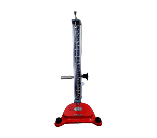
The Dart Impact Tester is used to determine the energy that causes plastic films to fail under specified conditions of impact. The Test is carried out by dropping a free falling dart with a diameter suitable to the type of film. The dart having hemispherical head is dripped from varying heights depending upon the range of applications for the dart missiles heights for the particular type of the film. The Dart is dropped automatically by an Electromagnetic Device which is controlled by push button. The tester is also fitted with one Electric Counter for the no. of trials taken during the test.
Description of the Machine :
The machine consists a two piece annular specimen clamp having an inside diameter of 12.7 cm and confirming the standard. The lower ( stationary ) half of the clamp is rigidly mounted so that the plane of the specimen is horizontal and at an angle of 90o with respect to the upright Dart supporting member of the machine.
The upper movable portion of the clamp is designed to maintain position and planer contact with the lower portion of the clamp when in position. Both the internal surface having smooth coating of soft material to give cushion which minimizes thickness variations and also allows firm gripping of the specimen. The clamping jaws and designed in waves principle to seat the specimen vary tightly and avoid slippage it even not required vacuum clamping.
Electro Magnetical Adaptor :
An Electromagnetical Device fitted for use in supporting the instantaneously releasing the dart so that it will fall freely on the centre of the test specimen in the specimen holder.
DART :
The Dart consisting of a 3.81 cm diameter hemispherical head fitted with 0.64 cm diameter shaft 11.5 cm long, to accommodate removable mass. The head is constructed of soft material. The shaft is attached to the centre of the flat upper surface. It is also provided with a 1.27 cm long steel tip at the end for supporting in the adaptor.
MASSES
Steel Masses are supplied along with the machine as follows.
- 1. Four masses of 5g. + 0.1g having a hole of diameter 0.64 cm.
- 2. Four masses of 15g. + 0.1g having a hole of diameter 0.64 cm
- 3. Four masses of 30g. + 0.1g having a hole of diameter 0.64 cm.
- 4. Four masses of 60g. + 0.1g having a hole of diameter 0.64 cm.
- 5. One mass of 100g. + 0.1g having a hole of diameter 0.64 cm.
- 6. One mass of 200g. + 0.1g having a hole of diameter 0.64 cm.
- 7. One mass of 300g. + 0.1g having a hole of diameter 0.64 cm.
- 8. One mass of 600g. + 0.1g having a hole of diameter 0.64 cm.
Low Impact Resistance Film
Normal Impact Resistance Film
High Impact Resistance Film
TEST SPECIMEN
Test specimen shall be large enough to extend outside the specimen clamp at all points. The specimens shall be representative of the material under test and shall be free from pinholes, wrinkles, folds or other obvious imperfections, unless such imperfections constitute variable under test
PROCEDURE
Place the specimen over the bottom portion of the clamp, making certain that it is uniformly flat, free of folds and that it covers at all points. Clamp the specimen in place by applying annular pressure with the top portion of the clamp. Position the dart vertically with the steel shaft tip inserted in the adapter and impinging surface of the dart at the appropriate height from the film surface. Release the dart . Care shall be taken to avoid multiple impact in cases where the dart bounces off the specimen. The operator should attempt to catch the dart in such cases to prevent damage to the impinging surface.
Examine the specimen to determine whether it has failed or not. Failure is defined as any break through the film. Such a break may be observed readily by viewing the specimen under back lighting conditions. Use new specimen for each impact. Before beginning the test, a few trial runs shall be made to establish approximately the working range of masses which will break the film. Then for at least three dart masses selected to give percentage failure between 20 and 80, a minimum of ten test specimens at each dart mass shall be tested.
DETERMINATION OF IMPACT FAILURE LOAD
Plot the percentage of failures against total mass of the falling dart on a graph paper and determine the results graphically. The dart mass at which 50 percent of the specimens fail shall be read from the graph and will give value for impact failure load.
